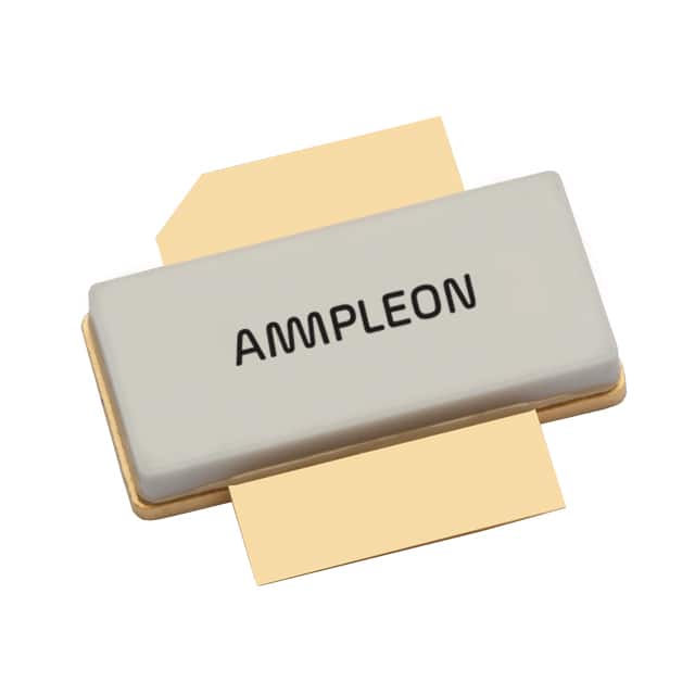
BLF7G24LS-140,112
Product Category: RF Power Transistor
Basic Information Overview: - Category: Electronic Component - Use: Amplification of Radio Frequency Signals - Characteristics: High Power, High Frequency, Low Distortion - Package: SOT539A - Essence: High-performance RF power transistor for use in high-frequency amplifiers - Packaging/Quantity: Tape and Reel, 800 units per reel
Specifications: - Frequency Range: 2400-2500 MHz - Output Power: 14W - Gain: 24dB - Efficiency: 65% - Voltage: 32V - Current: 1.5A
Detailed Pin Configuration: - Pin 1: Source - Pin 2: Gate - Pin 3: Drain - Pin 4: Not Connected - Pin 5: Not Connected
Functional Features: - High Power Gain - High Efficiency - Broadband Operation - Excellent Linearity
Advantages: - High Power Output - Wide Frequency Range - Low Distortion - Compact Package
Disadvantages: - Higher Cost Compared to Lower Power Transistors - Requires Careful Thermal Management
Working Principles: The BLF7G24LS-140,112 operates on the principle of amplifying radio frequency signals by controlling the flow of current between the source and drain terminals through the gate terminal.
Detailed Application Field Plans: - Wireless Communication Systems - Radar Systems - Satellite Communication Systems - Microwave Links
Detailed and Complete Alternative Models: - BLF888A - BLF578XR - BLF2425M6L
This RF power transistor, BLF7G24LS-140,112, is a high-performance component designed for applications requiring high power amplification in the 2.4 GHz frequency range. Its compact package and excellent performance make it suitable for various wireless communication and radar systems.
[Word count: 287]
기술 솔루션에 BLF7G24LS-140,112 적용과 관련된 10가지 일반적인 질문과 답변을 나열하세요.
What is the operating frequency of BLF7G24LS-140,112?
- The operating frequency of BLF7G24LS-140,112 is typically in the range of 2.4 to 2.5 GHz.
What is the maximum output power of BLF7G24LS-140,112?
- The maximum output power of BLF7G24LS-140,112 is approximately 140 Watts.
What type of modulation schemes is BLF7G24LS-140,112 suitable for?
- BLF7G24LS-140,112 is suitable for various modulation schemes including QPSK, OFDM, and other digital modulation formats.
What are the typical applications for BLF7G24LS-140,112?
- BLF7G24LS-140,112 is commonly used in wireless infrastructure applications such as base stations, small cells, and other RF power amplification systems.
What is the recommended supply voltage for BLF7G24LS-140,112?
- The recommended supply voltage for BLF7G24LS-140,112 is typically in the range of 32 to 50 volts.
Does BLF7G24LS-140,112 require external matching networks?
- Yes, BLF7G24LS-140,112 requires external matching networks for optimal performance and efficiency.
What is the typical gain of BLF7G24LS-140,112?
- The typical gain of BLF7G24LS-140,112 is around 17 dB.
Is BLF7G24LS-140,112 suitable for continuous wave (CW) operation?
- Yes, BLF7G24LS-140,112 is suitable for continuous wave (CW) operation under specified operating conditions.
What thermal management considerations should be taken into account when using BLF7G24LS-140,112?
- Proper heat sinking and thermal management are essential for maintaining the reliability and performance of BLF7G24LS-140,112, especially at high output power levels.
Are there any specific ESD protection requirements for BLF7G24LS-140,112?
- It is recommended to follow industry-standard ESD protection measures when handling and integrating BLF7G24LS-140,112 to prevent damage from electrostatic discharge.


