

Encyclopedia Entry: 74FCT166244CTPVG8
Basic Information Overview
- Category: Integrated Circuit (IC)
- Use: Buffer/Line Driver
- Characteristics: High-speed, low-power, non-inverting, 16-bit bus transceiver
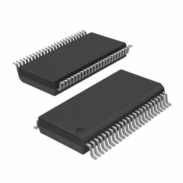
- Package: TSSOP (Thin Shrink Small Outline Package)
- Essence: The 74FCT166244CTPVG8 is a high-performance buffer and line driver IC designed to provide bidirectional communication between two buses operating at different voltage levels.
- Packaging/Quantity: Available in tape and reel packaging with 2500 units per reel.
Specifications
- Logic Family: FCT
- Number of Bits: 16
- Input Voltage Range: 4.5V to 5.5V
- Output Voltage Range: 4.5V to 5.5V
- Operating Temperature Range: -40°C to +85°C
- Propagation Delay Time: 3.5ns (max)
- Output Current: ±24mA
- Supply Current: 50μA (typ)
Detailed Pin Configuration
The 74FCT166244CTPVG8 has a total of 48 pins arranged as follows:
┌───┬───┐
   A1 --|1  └─ 48|-- VCCB
   B1 --|2     47|-- OE#
   A2 --|3     46|-- B2
   B2 --|4     45|-- A2
   A3 --|5     44|-- B3
   B3 --|6     43|-- A3
   A4 --|7     42|-- B4
   B4 --|8     41|-- A4
   A5 --|9     40|-- B5
   B5 --|10    39|-- A5
   A6 --|11    38|-- B6
   B6 --|12    37|-- A6
   A7 --|13    36|-- B7
   B7 --|14    35|-- A7
   A8 --|15    34|-- B8
   B8 --|16    33|-- A8
   GND --|17    32|-- B9
   Y1 --|18    31|-- A9
   Y2 --|19    30|-- B10
   Y3 --|20    29|-- A10
   Y4 --|21    28|-- B11
   Y5 --|22    27|-- A11
   Y6 --|23    26|-- B12
   Y7 --|24    25|-- A12
        └───┴───┘
Functional Features
- Bidirectional data flow between two independent buses.
- Non-inverting buffer/line driver with 3-state outputs.
- High-speed operation suitable for high-performance systems.
- Low-power consumption for energy-efficient designs.
- ESD protection on all inputs and outputs.
Advantages and Disadvantages
Advantages: - Enables communication between buses operating at different voltage levels. - Provides buffering and line driving capabilities. - High-speed operation allows for efficient data transfer. - Low-power consumption helps in reducing overall system power requirements. - ESD protection ensures robustness against electrostatic discharge.
Disadvantages: - Limited to 16-bit bus width. - Requires careful consideration of voltage compatibility between the two buses.
Working Principles
The 74FCT166244CTPVG8 acts as a bidirectional buffer and line driver, allowing data to be transferred between two independent buses. It operates by receiving data from one bus and transmitting it to the other, while also providing buffering and line driving capabilities to ensure signal integrity. The non-inverting nature of the IC ensures that the data remains unchanged during transmission. The 3-state outputs allow for easy control of the bus connection, enabling multiple devices to share the same bus without interference.
Detailed Application Field Plans
The 74FCT166244CTPVG8 is commonly used in various applications, including: - Data communication systems - Networking equipment - Industrial automation - Automotive electronics - Consumer electronics
Detailed and Complete Alternative Models
Some alternative models that offer similar functionality to the 74FCT166244CTPVG8 include: - SN74LVC244A: Low-voltage octal buffer/line driver - MC74VHC244: High-speed CMOS octal buffer/line driver - CD74HCT244: High-speed CMOS octal buffer/line driver with 3-state outputs
These alternative models can be considered based on specific requirements such as voltage levels, speed, power consumption,
기술 솔루션에 74FCT166244CTPVG8 적용과 관련된 10가지 일반적인 질문과 답변을 나열하세요.
Sure! Here are 10 common questions and answers related to the application of 74FCT166244CTPVG8 in technical solutions:
Q: What is the 74FCT166244CTPVG8? A: The 74FCT166244CTPVG8 is a 16-bit buffer/line driver with 3-state outputs, designed for high-performance applications.
Q: What is the purpose of using the 74FCT166244CTPVG8 in a technical solution? A: The 74FCT166244CTPVG8 can be used to buffer and drive signals between different parts of a circuit, ensuring proper signal integrity and voltage levels.
Q: What is the maximum operating frequency of the 74FCT166244CTPVG8? A: The maximum operating frequency of the 74FCT166244CTPVG8 is typically around 200 MHz.
Q: Can the 74FCT166244CTPVG8 handle both input and output signals? A: Yes, the 74FCT166244CTPVG8 can be used for both input and output signals, making it versatile in various applications.
Q: What is the voltage supply range for the 74FCT166244CTPVG8? A: The 74FCT166244CTPVG8 operates with a voltage supply range of 4.5V to 5.5V.
Q: Does the 74FCT166244CTPVG8 have built-in protection features? A: Yes, the 74FCT166244CTPVG8 has built-in ESD (Electrostatic Discharge) protection on its inputs and outputs.
Q: Can the 74FCT166244CTPVG8 be used in high-speed data transmission applications? A: Yes, the 74FCT166244CTPVG8 is suitable for high-speed data transmission due to its fast propagation delay and low output skew.
Q: What is the power consumption of the 74FCT166244CTPVG8? A: The power consumption of the 74FCT166244CTPVG8 is relatively low, making it energy-efficient in electronic systems.
Q: Can the 74FCT166244CTPVG8 drive capacitive loads? A: Yes, the 74FCT166244CTPVG8 can drive capacitive loads up to a certain limit, but it's recommended to consult the datasheet for specific details.
Q: Are there any special considerations when designing with the 74FCT166244CTPVG8? A: It's important to ensure proper decoupling and bypassing of the power supply, minimize signal reflections, and follow the recommended layout guidelines provided in the datasheet for optimal performance.
Please note that the answers provided here are general and may vary depending on the specific application and requirements. Always refer to the datasheet and consult with technical experts for accurate information.