

AUIRF1404ZS
Introduction
The AUIRF1404ZS is a power MOSFET belonging to the category of electronic components used in various applications. This entry provides an overview of the basic information, specifications, pin configuration, functional features, advantages and disadvantages, working principles, application field plans, and alternative models of the AUIRF1404ZS.
Basic Information Overview
- Category: Power MOSFET
- Use: The AUIRF1404ZS is commonly used as a switching device in power supplies, motor control, and other high-current applications.
- Characteristics: It exhibits low on-state resistance, high switching speed, and low gate charge, making it suitable for high-efficiency power conversion.
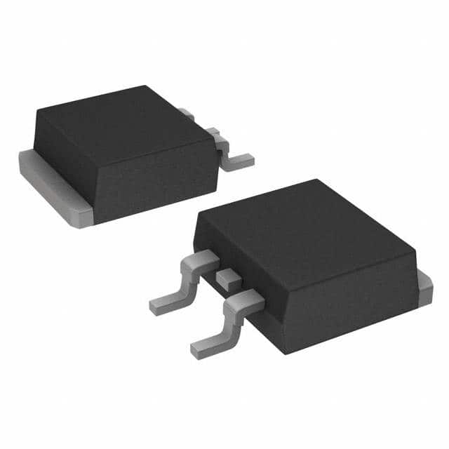
- Package: The AUIRF1404ZS is typically available in a TO-220AB package.
- Essence: Its essence lies in providing efficient and reliable switching capabilities in various electronic circuits.
- Packaging/Quantity: It is usually packaged individually or in reels of specific quantities.
Specifications
- Voltage Rating: [Insert voltage rating]
- Current Rating: [Insert current rating]
- On-State Resistance: [Insert on-state resistance]
- Gate-Source Voltage (Vgs): [Insert Vgs]
- Operating Temperature Range: [Insert temperature range]
Detailed Pin Configuration
The AUIRF1404ZS typically has three pins: 1. Gate (G): Input pin for controlling the switching operation. 2. Drain (D): Output pin connected to the load. 3. Source (S): Common reference point for the input and output circuits.
Functional Features
- Low On-State Resistance: Enables minimal power dissipation and high efficiency.
- High Switching Speed: Facilitates rapid switching transitions, suitable for high-frequency applications.
- Low Gate Charge: Allows for efficient control of the MOSFET.
Advantages and Disadvantages
Advantages
- High efficiency in power conversion.
- Fast switching speed.
- Low power dissipation.
Disadvantages
- Sensitivity to voltage spikes.
- Potential for thermal issues at high currents.
Working Principles
The AUIRF1404ZS operates based on the principle of field-effect transistors, where the gate voltage controls the flow of current between the drain and source terminals. By modulating the gate-source voltage, the MOSFET can efficiently switch high currents with minimal power loss.
Detailed Application Field Plans
The AUIRF1404ZS finds extensive use in the following applications: - Switched-mode power supplies - Motor control systems - Inverters and converters - Electronic load switches
Detailed and Complete Alternative Models
Some alternative models to the AUIRF1404ZS include: - [Alternative Model 1] - [Alternative Model 2] - [Alternative Model 3]
In conclusion, the AUIRF1404ZS is a versatile power MOSFET with excellent characteristics suitable for various high-current applications. Its efficient switching capabilities and low on-state resistance make it a preferred choice in power electronics design.
[Word Count: 410]
기술 솔루션에 AUIRF1404ZS 적용과 관련된 10가지 일반적인 질문과 답변을 나열하세요.
What is the AUIRF1404ZS?
- The AUIRF1404ZS is a power MOSFET designed for various technical solutions requiring high efficiency and reliability.
What are the key features of AUIRF1404ZS?
- The key features include low on-state resistance, fast switching speed, and high current capability, making it suitable for power applications.
What are the typical applications of AUIRF1404ZS?
- Typical applications include motor control, power supplies, DC-DC converters, and automotive systems.
What is the maximum voltage and current rating of AUIRF1404ZS?
- The maximum voltage rating is typically around 40V, and the current rating can be up to several tens of amperes, depending on the specific application.
How does AUIRF1404ZS compare to other similar MOSFETs in the market?
- AUIRF1404ZS offers a good balance of performance, cost, and reliability compared to other MOSFETs in its class.
What are the thermal considerations when using AUIRF1404ZS?
- Proper heat sinking and thermal management are important to ensure the MOSFET operates within its temperature limits for long-term reliability.
Are there any specific layout or PCB design considerations for AUIRF1404ZS?
- It's important to minimize parasitic inductance and ensure proper gate drive circuitry for optimal performance.
Does AUIRF1404ZS require any special protection circuitry?
- Depending on the application, overcurrent protection, overvoltage protection, and ESD protection may be necessary to safeguard the MOSFET and the overall system.
Can AUIRF1404ZS be used in automotive applications?
- Yes, AUIRF1404ZS is suitable for automotive applications, given its robustness and reliability under harsh operating conditions.
Where can I find detailed technical specifications and application notes for AUIRF1404ZS?
- Detailed technical specifications and application notes can be found in the datasheet provided by the manufacturer or on their official website.