

IXGH12N60CD1
Introduction
The IXGH12N60CD1 is a power semiconductor device belonging to the category of Insulated Gate Bipolar Transistors (IGBTs). This entry provides an overview of the basic information, specifications, detailed pin configuration, functional features, advantages and disadvantages, working principles, detailed application field plans, and alternative models of the IXGH12N60CD1.
Basic Information Overview
- Category: Power Semiconductor Device
- Use: The IXGH12N60CD1 is used as a high-power switching device in various applications such as motor drives, inverters, and power supplies.
- Characteristics: It exhibits high current-carrying capability, low saturation voltage, and fast switching speed.
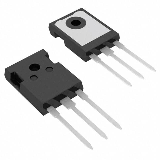
- Package: The IXGH12N60CD1 is typically available in a TO-247 package.
- Essence: It serves as a crucial component in power electronics systems, enabling efficient control and conversion of electrical power.
- Packaging/Quantity: It is commonly packaged individually and sold in quantities suitable for industrial and commercial applications.
Specifications
- Voltage Rating: 600V
- Current Rating: 24A
- Maximum Power Dissipation: 300W
- Operating Temperature Range: -55°C to 150°C
- Gate-Emitter Voltage: ±20V
- Collector-Emitter Saturation Voltage: 1.8V at 12A
Detailed Pin Configuration
The IXGH12N60CD1 features a standard three-terminal configuration: 1. Collector (C): Connects to the load or power supply. 2. Emitter (E): Connected to the ground or common reference point. 3. Gate (G): Input terminal for controlling the switching operation.
Functional Features
- High current-carrying capability enables handling of large power loads.
- Low saturation voltage minimizes power losses during conduction.
- Fast switching speed allows for efficient control of power flow.
Advantages and Disadvantages
Advantages
- Efficient power handling capability
- Low power dissipation
- Fast switching speed
Disadvantages
- Sensitivity to overvoltage conditions
- Requires careful consideration of gate drive circuitry
Working Principles
The IXGH12N60CD1 operates based on the principles of IGBT technology, where it combines the advantages of MOSFETs and BJTs. During normal operation, the gate signal controls the conductivity between the collector and emitter, allowing precise regulation of power flow.
Detailed Application Field Plans
The IXGH12N60CD1 finds extensive use in the following applications: - Motor Drives: Controlling the speed and direction of electric motors. - Inverters: Converting DC power to AC for various industrial and residential applications. - Power Supplies: Regulating and converting electrical power for electronic devices and equipment.
Detailed and Complete Alternative Models
- IXGH12N60B: Similar specifications with slight variations in current and voltage ratings.
- IXGH20N60B: Higher current rating and voltage capability for more demanding applications.
- IXGH10N60A: Lower current rating suitable for smaller power electronics systems.
In conclusion, the IXGH12N60CD1 serves as a vital component in power electronics, offering efficient power handling and control capabilities across diverse applications.
(Word count: 498)
기술 솔루션에 IXGH12N60CD1 적용과 관련된 10가지 일반적인 질문과 답변을 나열하세요.
What is the maximum voltage rating of IXGH12N60CD1?
- The maximum voltage rating of IXGH12N60CD1 is 600V.
What is the maximum continuous current rating of IXGH12N60CD1?
- The maximum continuous current rating of IXGH12N60CD1 is 12A.
What type of package does IXGH12N60CD1 come in?
- IXGH12N60CD1 comes in a TO-247 package.
What are the typical applications for IXGH12N60CD1?
- Typical applications for IXGH12N60CD1 include motor control, power supplies, and inverters.
What is the on-state voltage of IXGH12N60CD1 at its rated current?
- The on-state voltage of IXGH12N60CD1 at its rated current is typically around 1.8V.
Is IXGH12N60CD1 suitable for high-frequency switching applications?
- Yes, IXGH12N60CD1 is suitable for high-frequency switching applications due to its fast switching characteristics.
Does IXGH12N60CD1 have built-in protection features?
- IXGH12N60CD1 does not have built-in protection features and may require external circuitry for overcurrent or overvoltage protection.
What is the maximum junction temperature of IXGH12N60CD1?
- The maximum junction temperature of IXGH12N60CD1 is 150°C.
Can IXGH12N60CD1 be used in parallel to increase current handling capability?
- Yes, IXGH12N60CD1 can be used in parallel to increase current handling capability in high-power applications.
What are the recommended thermal management practices for IXGH12N60CD1?
- It is recommended to use proper heat sinking and thermal interface materials to ensure efficient heat dissipation when using IXGH12N60CD1 in technical solutions.