

IXGT40N60B2
Product Overview
- Category: Power semiconductor device
- Use: High-power switching applications
- Characteristics: High voltage, high current capability, low on-state voltage drop
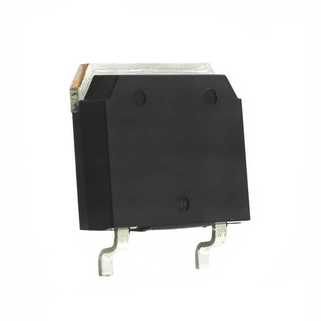
- Package: TO-3P
- Essence: Insulated Gate Bipolar Transistor (IGBT)
- Packaging/Quantity: Typically sold individually
Specifications
- Voltage Rating: 600V
- Current Rating: 40A
- Maximum Power Dissipation: 300W
- Operating Temperature Range: -55°C to 150°C
Detailed Pin Configuration
The IXGT40N60B2 typically has three pins: 1. Collector (C) 2. Gate (G) 3. Emitter (E)
Functional Features
- High voltage capability
- Low saturation voltage
- Fast switching speed
- High input impedance
Advantages and Disadvantages
Advantages: - Suitable for high-power applications - Low conduction losses - Fast switching times
Disadvantages: - Higher cost compared to some alternatives - Requires careful handling due to high power capabilities
Working Principles
The IXGT40N60B2 operates based on the principles of an Insulated Gate Bipolar Transistor (IGBT), which combines the advantages of MOSFETs and bipolar transistors. When a voltage is applied to the gate, it controls the flow of current between the collector and emitter, allowing for efficient switching and control of high power.
Detailed Application Field Plans
The IXGT40N60B2 is commonly used in various high-power applications such as: - Motor drives - Power supplies - Renewable energy systems - Industrial automation
Detailed and Complete Alternative Models
Some alternative models to the IXGT40N60B2 include: - IRG4PH40UD (Infineon) - FGA40N65SMD (Fairchild Semiconductor) - NGTB40N60FLWG (ON Semiconductor)
This information provides a comprehensive overview of the IXGT40N60B2, covering its product details, specifications, functional features, application fields, and alternative models.
기술 솔루션에 IXGT40N60B2 적용과 관련된 10가지 일반적인 질문과 답변을 나열하세요.
What is the maximum voltage rating of IXGT40N60B2?
- The maximum voltage rating of IXGT40N60B2 is 600V.
What is the maximum continuous collector current of IXGT40N60B2?
- The maximum continuous collector current of IXGT40N60B2 is 40A.
What type of package does IXGT40N60B2 come in?
- IXGT40N60B2 comes in a TO-268 package.
What are the typical applications of IXGT40N60B2?
- IXGT40N60B2 is commonly used in motor control, power supplies, and inverters.
What is the on-state voltage drop of IXGT40N60B2 at 25°C?
- The on-state voltage drop of IXGT40N60B2 at 25°C is typically 1.8V.
Is IXGT40N60B2 suitable for high-frequency switching applications?
- Yes, IXGT40N60B2 is suitable for high-frequency switching due to its fast switching characteristics.
What is the maximum junction temperature of IXGT40N60B2?
- The maximum junction temperature of IXGT40N60B2 is 150°C.
Does IXGT40N60B2 have built-in protection features?
- IXGT40N60B2 does not have built-in protection features and may require external circuitry for overcurrent or overvoltage protection.
Can IXGT40N60B2 be used in parallel configurations for higher current applications?
- Yes, IXGT40N60B2 can be used in parallel configurations to achieve higher current handling capabilities.
What are the recommended thermal management considerations for IXGT40N60B2?
- Adequate heat sinking and proper PCB layout are essential for effective thermal management when using IXGT40N60B2 in technical solutions.