

MXSMCJ45CAE3
Product Overview
Category
The MXSMCJ45CAE3 belongs to the category of Ethernet connectors.
Use
It is used for connecting Ethernet cables to devices such as computers, routers, and switches.
Characteristics
- Compact design
- High-speed data transmission
- Durable construction
- Easy installation
Package
The MXSMCJ45CAE3 is typically available in a protective plastic packaging.
Essence
This product serves as a crucial component for establishing wired network connections.
Packaging/Quantity
The MXSMCJ45CAE3 is usually packaged individually or in sets of multiple connectors.
Specifications
- Connector Type: RJ45
- Mounting Type: Through Hole
- Number of Positions/Contacts: 8p8c (RJ45, Ethernet)
- Shielding: Shielded
- Termination: Solder
- Features: Board Lock
- LED Color: Does not contain LED
- Packaging: Tape & Reel (TR)
Detailed Pin Configuration
The detailed pin configuration for the MXSMCJ45CAE3 is as follows: 1. Pin 1 - TX+ 2. Pin 2 - TX- 3. Pin 3 - RX+ 4. Pin 4 - Not Connected 5. Pin 5 - Not Connected 6. Pin 6 - RX- 7. Pin 7 - Not Connected 8. Pin 8 - Not Connected
Functional Features
- Secure connection for reliable data transfer
- Compatibility with standard Ethernet cables
- Robust shielding for minimizing interference
- Solder termination for strong and durable connections
Advantages and Disadvantages
Advantages
- High-speed data transmission
- Secure and reliable connectivity
- Durable construction for long-term use
Disadvantages
- Requires soldering for termination
- Limited flexibility in cable routing due to through-hole mounting
Working Principles
The MXSMCJ45CAE3 functions by providing a secure and stable connection between an Ethernet cable and a device's Ethernet port. The shielded design helps minimize electromagnetic interference, ensuring high-quality data transmission.
Detailed Application Field Plans
The MXSMCJ45CAE3 is commonly used in various networking applications, including: - Computer networking - Telecommunications equipment - Industrial automation systems - Consumer electronics
Detailed and Complete Alternative Models
Some alternative models to the MXSMCJ45CAE3 include: - MXTMCJ45CAE3 - MXSMCJ45CAE4 - MXSMCJ45CAE5
In conclusion, the MXSMCJ45CAE3 is a reliable Ethernet connector that offers high-speed data transmission and secure connectivity, making it suitable for a wide range of networking applications.
Word Count: 413
기술 솔루션에 MXSMCJ45CAE3 적용과 관련된 10가지 일반적인 질문과 답변을 나열하세요.
What is MXSMCJ45CAE3?
- MXSMCJ45CAE3 is a surface mount Transient Voltage Suppressor (TVS) diode designed to protect sensitive electronics from voltage transients induced by lightning and other transient voltage events.
What is the maximum peak pulse power of MXSMCJ45CAE3?
- The maximum peak pulse power of MXSMCJ45CAE3 is 1500 watts.
What is the breakdown voltage of MXSMCJ45CAE3?
- The breakdown voltage of MXSMCJ45CAE3 is 45 volts.
What are the typical applications of MXSMCJ45CAE3?
- MXSMCJ45CAE3 is commonly used in Ethernet, LAN, and WAN applications, as well as in protection circuits for telecommunication equipment and industrial control systems.
What is the operating temperature range of MXSMCJ45CAE3?
- The operating temperature range of MXSMCJ45CAE3 is -55°C to +150°C.
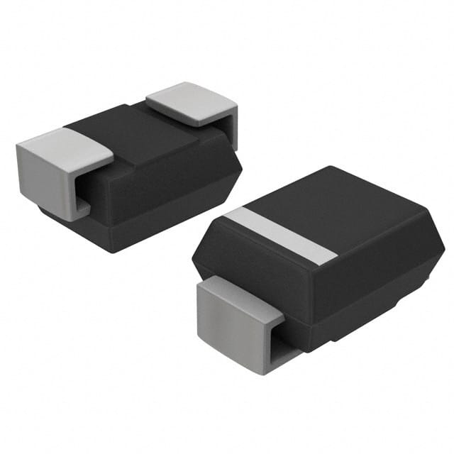
What is the package type of MXSMCJ45CAE3?
- MXSMCJ45CAE3 comes in a SMC (DO-214AB) package.
What is the clamping voltage of MXSMCJ45CAE3?
- The clamping voltage of MXSMCJ45CAE3 is 77.4 volts at 10A.
Is MXSMCJ45CAE3 RoHS compliant?
- Yes, MXSMCJ45CAE3 is RoHS compliant, making it suitable for use in environmentally friendly electronic products.
What are the key features of MXSMCJ45CAE3?
- Some key features of MXSMCJ45CAE3 include low clamping voltage, fast response time, and high surge capability.
How should MXSMCJ45CAE3 be mounted on a PCB?
- MXSMCJ45CAE3 should be mounted using appropriate soldering techniques and should be placed close to the protected circuit to minimize lead inductance and maximize its protective effect.