

MJ802G Product Overview
Introduction
The MJ802G is a versatile electronic component that belongs to the category of power transistors. This entry provides an in-depth overview of the MJ802G, including its basic information, specifications, pin configuration, functional features, advantages and disadvantages, working principles, application field plans, and alternative models.
Basic Information Overview
- Category: Power Transistor
- Use: Amplification and switching of electronic signals
- Characteristics: High power handling capability, low collector-emitter saturation voltage, and high current gain
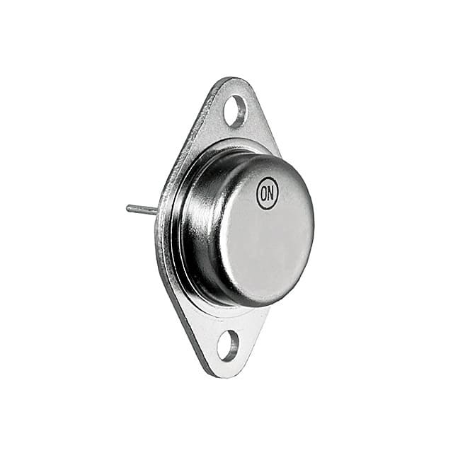
- Package: TO-3 metal can package
- Essence: Silicon NPN power transistor
- Packaging/Quantity: Typically sold individually or in small quantities
Specifications
- Maximum Collector-Emitter Voltage (Vce): 100V
- Maximum Collector Current (Ic): 10A
- Power Dissipation (Pd): 150W
- Transition Frequency (ft): 2MHz
- Operating Temperature Range: -65°C to 200°C
Detailed Pin Configuration
The MJ802G power transistor typically has three pins: 1. Base (B): Input terminal for controlling the transistor's operation 2. Collector (C): Output terminal for the amplified signal 3. Emitter (E): Ground reference terminal
Functional Features
- High power amplification capability
- Low saturation voltage for efficient switching
- Robust construction for reliable performance in demanding applications
Advantages and Disadvantages
Advantages
- High power handling capacity
- Low collector-emitter saturation voltage
- High current gain for efficient signal amplification
Disadvantages
- Relatively large package size
- Limited operating temperature range compared to some alternative models
Working Principles
The MJ802G operates based on the principles of bipolar junction transistors. When a small current flows into the base terminal, it controls a much larger current between the collector and emitter terminals, allowing for signal amplification or switching.
Detailed Application Field Plans
The MJ802G finds extensive use in various electronic applications, including: - Audio amplifiers - Power supplies - Motor control circuits - RF amplifiers
Detailed and Complete Alternative Models
Some alternative models to the MJ802G include: - TIP31C - 2N3055 - MJE13009 - BD139
In conclusion, the MJ802G power transistor offers high power handling capabilities, making it suitable for a wide range of electronic applications. Its robust construction and efficient amplification characteristics make it a popular choice among electronic enthusiasts and professionals alike.
Word Count: 345
기술 솔루션에 MJ802G 적용과 관련된 10가지 일반적인 질문과 답변을 나열하세요.
What is the MJ802G transistor used for?
- The MJ802G is a high-power NPN silicon transistor commonly used in audio amplifiers, power supplies, and other high-voltage applications.
What are the key specifications of the MJ802G transistor?
- The MJ802G has a maximum collector-emitter voltage of 140V, a continuous collector current of 15A, and a power dissipation of 150W.
How do I properly mount the MJ802G transistor?
- The MJ802G should be mounted on a suitable heat sink to ensure proper heat dissipation and prevent overheating.
Can the MJ802G be used in switching applications?
- Yes, the MJ802G can be used in switching applications due to its high voltage and current capabilities.
What are the typical operating conditions for the MJ802G?
- The MJ802G operates within a temperature range of -65°C to 200°C and requires a base current of 3A for proper saturation.
Are there any common failure modes for the MJ802G?
- Common failure modes include thermal runaway due to inadequate heat sinking and overvoltage stress leading to breakdown.
Can the MJ802G be used in automotive applications?
- Yes, the MJ802G is suitable for automotive applications such as electronic ignition systems and motor control.
What are the recommended complementary transistors to use with the MJ802G?
- Complementary transistors such as the MJ4502G or MJ15024G can be used with the MJ802G to form high-power amplifier stages.
How do I test the MJ802G transistor for proper operation?
- The MJ802G can be tested using a multimeter to check for proper junction voltages and current gain.
Where can I find detailed application notes for using the MJ802G in technical solutions?
- Detailed application notes for the MJ802G can be found in the manufacturer's datasheet and application guides, as well as in technical forums and electronics publications.