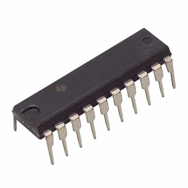
CD74HC4351E
Product Overview
- Category: Integrated Circuit
- Use: Multiplexer/Demultiplexer
- Characteristics: High-speed CMOS logic, 8-channel analog multiplexer/demultiplexer
- Package: DIP (Dual In-line Package)
- Essence: Analog Switch
- Packaging/Quantity: Tube, 25 pieces per tube
Specifications
- Supply Voltage Range: 2V to 6V
- On-State Resistance: 70Ω (typical)
- Channel-to-Channel Crosstalk: -80dB (typical)
- Input Capacitance: 10pF (typical)
- Operating Temperature Range: -40°C to +85°C
Detailed Pin Configuration
The CD74HC4351E has a total of 16 pins. The pin configuration is as follows:
``` __ __ |1 __/ 16| |2 15| |3 14| |4 13| |5 12| |6 11| |7 10| |8 9|
```
Pin Description: 1. S0: Select input bit 0 2. S1: Select input bit 1 3. S2: Select input bit 2 4. E: Enable input 5. Y0: Output channel 0 6. Y1: Output channel 1 7. Y2: Output channel 2 8. Y3: Output channel 3 9. Y4: Output channel 4 10. Y5: Output channel 5 11. Y6: Output channel 6 12. Y7: Output channel 7 13. GND: Ground 14. VCC: Positive power supply 15. INH: Inhibit input 16. S3: Select input bit 3
Functional Features
- High-speed CMOS logic allows for fast switching between channels.
- 8-channel analog multiplexer/demultiplexer provides versatile signal routing options.
- Low on-state resistance ensures minimal signal distortion.
- Wide supply voltage range allows for compatibility with various systems.
- Channel-to-channel crosstalk is minimized, ensuring clean and accurate signal transmission.
Advantages and Disadvantages
Advantages: - Versatile multiplexing/demultiplexing capabilities. - Fast switching speed. - Low on-state resistance. - Wide supply voltage range.
Disadvantages: - Limited number of channels (8 channels). - Requires external control signals for channel selection.
Working Principles
The CD74HC4351E is an analog switch that operates based on the control signals provided to the select inputs (S0-S3). The combination of these select inputs determines which channel is connected to the output. The enable input (E) and inhibit input (INH) control the overall operation of the device. When enabled, the selected channel's input is connected to the corresponding output. When inhibited, all channels are disconnected from the outputs.
Detailed Application Field Plans
The CD74HC4351E finds applications in various fields, including:
- Audio Systems: Used for audio signal routing and switching in mixers, amplifiers, and audio interfaces.
- Test and Measurement Equipment: Enables flexible signal routing for testing and measurement purposes.
- Communication Systems: Facilitates channel selection and signal routing in communication devices such as routers and switches.
- Industrial Automation: Allows for efficient control and monitoring of analog signals in industrial automation systems.
- Medical Devices: Used for signal routing and switching in medical equipment like patient monitors and diagnostic instruments.
Detailed and Complete Alternative Models
Some alternative models to the CD74HC4351E include:
- CD4051B: 8-channel analog multiplexer/demultiplexer with lower on-state resistance.
- CD4067B: 16-channel analog multiplexer/demultiplexer for applications requiring more channels.
- ADG508A: CMOS analog multiplexer/demultiplexer with low distortion and high bandwidth.
- SN74LVC1G3157: Single-channel analog switch with low on-resistance and wide voltage range.
These alternative models offer similar functionality but may have different specifications and package options.
Word count: 515 words
기술 솔루션에 CD74HC4351E 적용과 관련된 10가지 일반적인 질문과 답변을 나열하세요.
Sure! Here are 10 common questions and answers related to the application of CD74HC4351E in technical solutions:
Q1: What is CD74HC4351E? A1: CD74HC4351E is a multiplexer/demultiplexer integrated circuit (IC) that allows multiple analog or digital signals to be routed through a single channel.
Q2: What is the purpose of CD74HC4351E? A2: The purpose of CD74HC4351E is to enable signal routing and selection in various electronic applications, such as audio/video switching, data acquisition systems, and communication devices.
Q3: How many channels does CD74HC4351E have? A3: CD74HC4351E has 8 channels, which means it can handle up to 8 different input/output signals.
Q4: What is the voltage range supported by CD74HC4351E? A4: CD74HC4351E supports a wide voltage range from 2V to 6V, making it compatible with various power supply levels.
Q5: Can CD74HC4351E handle both analog and digital signals? A5: Yes, CD74HC4351E can handle both analog and digital signals, allowing for versatile signal routing capabilities.
Q6: How does CD74HC4351E select the desired channel? A6: CD74HC4351E uses control pins to select the desired channel. By setting the appropriate control signals, you can route the input signal to the desired output channel.
Q7: What is the maximum frequency supported by CD74HC4351E? A7: CD74HC4351E can support frequencies up to 100 MHz, making it suitable for high-speed signal routing applications.
Q8: Can CD74HC4351E be cascaded to increase the number of channels? A8: Yes, CD74HC4351E can be cascaded by connecting the output of one IC to the input of another, allowing for expansion of the number of channels.
Q9: Is CD74HC4351E compatible with microcontrollers and digital logic circuits? A9: Yes, CD74HC4351E is compatible with microcontrollers and digital logic circuits, making it easy to integrate into various electronic systems.
Q10: Are there any special considerations when using CD74HC4351E? A10: It is important to ensure that the voltage levels of the signals being routed through CD74HC4351E are within its specified range. Additionally, proper decoupling capacitors should be used to minimize noise and ensure stable operation.
Please note that these answers are general and may vary depending on specific application requirements and datasheet specifications.


