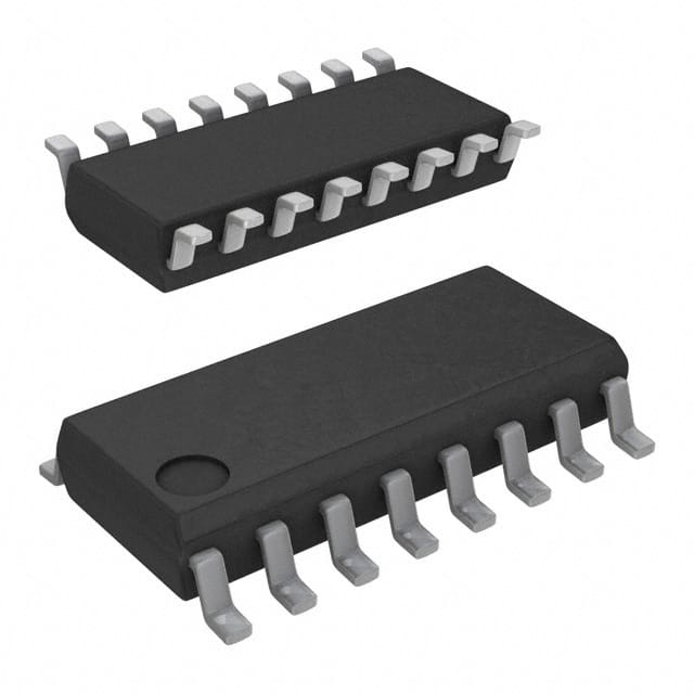
CD74HCT40105M
Product Overview
Category
CD74HCT40105M belongs to the category of integrated circuits (ICs).
Use
It is commonly used in electronic devices for various applications.
Characteristics
- High-speed operation
- Wide operating voltage range
- Low power consumption
- Compatibility with TTL inputs
- Schmitt trigger action on all inputs
Package
CD74HCT40105M is available in a small outline integrated circuit (SOIC) package.
Essence
The essence of CD74HCT40105M lies in its ability to provide reliable and efficient digital signal processing.
Packaging/Quantity
CD74HCT40105M is typically packaged in reels or tubes, with a quantity of 250 or 2000 units per reel/tube, respectively.
Specifications
- Supply Voltage: 2V to 6V
- Input Voltage: 0V to VCC
- Output Voltage: 0V to VCC
- Operating Temperature Range: -40°C to +85°C
- Logic Family: HCT
Detailed Pin Configuration
CD74HCT40105M consists of 16 pins arranged as follows:
- Pin 1: Input A1
- Pin 2: Input B1
- Pin 3: Input C1
- Pin 4: Input D1
- Pin 5: Output Y1
- Pin 6: Output Y2
- Pin 7: Output Y3
- Pin 8: Output Y4
- Pin 9: GND (Ground)
- Pin 10: Output Y5
- Pin 11: Output Y6
- Pin 12: Output Y7
- Pin 13: Output Y8
- Pin 14: Input D2
- Pin 15: Input C2
- Pin 16: VCC (Supply Voltage)
Functional Features
- Hex non-inverting level shifter
- Wide voltage range translation
- High noise immunity
- Balanced propagation delays
- Low power consumption
Advantages and Disadvantages
Advantages
- High-speed operation allows for efficient data processing.
- Wide operating voltage range enables compatibility with various systems.
- Low power consumption helps conserve energy.
- Schmitt trigger action on all inputs ensures reliable signal processing.
Disadvantages
- Limited number of input/output channels compared to some other ICs.
- May require additional components for certain applications.
Working Principles
CD74HCT40105M operates based on the principles of digital logic circuits. It receives input signals, processes them using internal circuitry, and produces corresponding output signals.
Detailed Application Field Plans
CD74HCT40105M finds applications in various fields, including but not limited to: 1. Communication systems 2. Industrial automation 3. Consumer electronics 4. Automotive electronics 5. Medical devices
Detailed and Complete Alternative Models
Some alternative models that can be considered as alternatives to CD74HCT40105M are: 1. SN74HCT125N 2. MC74HCT125AN 3. 74HCT125D 4. CD74HCT125E 5. TC74HCT125AF
These models offer similar functionality and characteristics, providing flexibility in choosing the most suitable option for specific requirements.
In conclusion, CD74HCT40105M is a versatile integrated circuit that offers high-speed operation, wide voltage range, and low power consumption. Its functional features, advantages, and application field plans make it a valuable component in various electronic systems.
기술 솔루션에 CD74HCT40105M 적용과 관련된 10가지 일반적인 질문과 답변을 나열하세요.
Sure! Here are 10 common questions and answers related to the application of CD74HCT40105M in technical solutions:
Q: What is CD74HCT40105M? A: CD74HCT40105M is a high-speed CMOS logic device, specifically a 4-bit synchronous binary counter with asynchronous reset.
Q: What is the operating voltage range for CD74HCT40105M? A: The operating voltage range for CD74HCT40105M is typically between 2V and 6V.
Q: What is the maximum clock frequency supported by CD74HCT40105M? A: CD74HCT40105M can support clock frequencies up to 25 MHz.
Q: Can CD74HCT40105M be used as a frequency divider? A: Yes, CD74HCT40105M can be used as a frequency divider by connecting the appropriate clock signal to the input.
Q: Does CD74HCT40105M have an asynchronous reset feature? A: Yes, CD74HCT40105M has an asynchronous reset pin (MR) that can be used to reset the counter to its initial state.
Q: How many outputs does CD74HCT40105M have? A: CD74HCT40105M has four outputs (Q0, Q1, Q2, and Q3), each representing a different bit of the counter value.
Q: Can CD74HCT40105M be cascaded to create larger counters? A: Yes, multiple CD74HCT40105M devices can be cascaded together to create larger counters with more bits.
Q: What is the power supply current consumption of CD74HCT40105M? A: The power supply current consumption of CD74HCT40105M is typically around 4 mA.
Q: Is CD74HCT40105M compatible with TTL logic levels? A: Yes, CD74HCT40105M is compatible with both CMOS and TTL logic levels.
Q: What are some typical applications of CD74HCT40105M? A: CD74HCT40105M can be used in various applications such as frequency division, counter circuits, clock generation, and digital signal processing.
Please note that the answers provided here are general and may vary depending on specific datasheet specifications and application requirements.


