

CDCVF2509PWR
Overview
Category
CDCVF2509PWR belongs to the category of integrated circuits (ICs).
Use
It is commonly used as a clock driver in electronic devices.
Characteristics
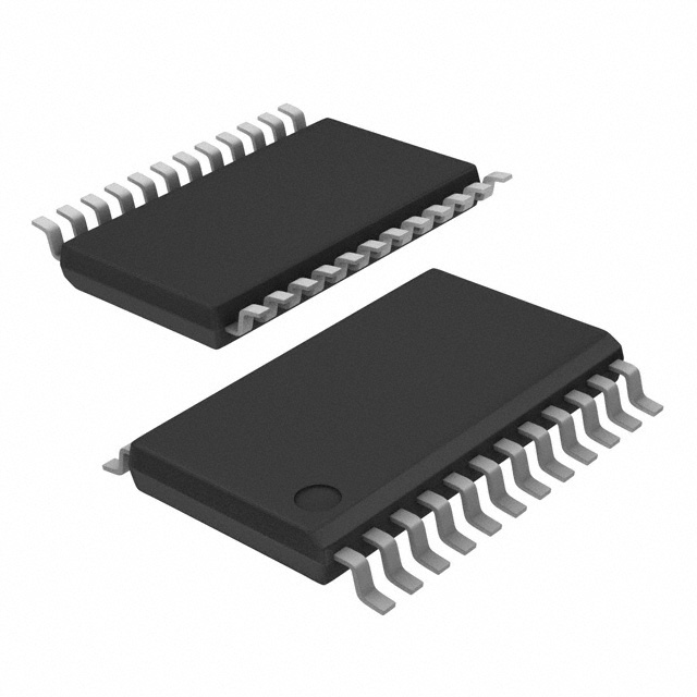
- Package: CDCVF2509PWR comes in a small outline package (SOP).
- Essence: This IC is designed to provide precise and stable clock signals.
- Packaging/Quantity: It is typically sold in reels, with each reel containing a specific quantity of CDCVF2509PWR ICs.
Specifications and Parameters
The following are the specifications and parameters of CDCVF2509PWR:
- Input Voltage Range: 2.3V to 3.6V
- Output Voltage Range: 0V to VCC
- Operating Temperature Range: -40°C to +85°C
- Supply Current: 10mA (typical)
Pin Configuration
The pin configuration of CDCVF2509PWR is as follows:
- VCC
- GND
- CLKIN
- CLKOUT
- OE
Functional Characteristics
CDCVF2509PWR offers the following functional characteristics:
- Clock Signal Amplification: It amplifies the input clock signal to provide a stronger output signal.
- Signal Level Shifting: The IC can shift the voltage level of the clock signal to match the requirements of the connected circuitry.
- Output Enable Control: The OE pin allows for enabling or disabling the output clock signal.
Advantages and Disadvantages
Advantages: - Precise and stable clock signal generation. - Compact SOP package for easy integration into electronic devices. - Wide operating temperature range.
Disadvantages: - Limited input voltage range. - Requires an external power supply.
Applicable Range of Products
CDCVF2509PWR is suitable for use in various electronic devices that require clock signal amplification and level shifting. It is commonly used in microcontrollers, digital signal processors, and communication devices.
Working Principles
The working principle of CDCVF2509PWR involves amplifying the input clock signal using internal circuitry and then shifting its voltage level to match the requirements of the connected circuitry. The output enable control allows for enabling or disabling the output clock signal as needed.
Detailed Application Field Plans
CDCVF2509PWR can be applied in the following fields:
- Microcontroller Systems: It ensures precise timing synchronization between different components of a microcontroller system.
- Digital Signal Processing: The IC helps maintain accurate clock signals in digital signal processing applications.
- Communication Devices: It enables reliable clock signal transmission in communication devices such as routers and switches.
Detailed Alternative Models
Some alternative models to CDCVF2509PWR include:
- CDCVF2505PWR
- CDCVF2510PWR
- CDCVF2507PWR
- CDCVF2508PWR
- CDCVF2506PWR
5 Common Technical Questions and Answers
Q: What is the maximum operating temperature of CDCVF2509PWR? A: The maximum operating temperature is +85°C.
Q: Can CDCVF2509PWR operate with an input voltage below 2.3V? A: No, the input voltage range should be between 2.3V and 3.6V.
Q: How many pins does CDCVF2509PWR have? A: It has five pins: VCC, GND, CLKIN, CLKOUT, and OE.
Q: What is the typical supply current of CDCVF2509PWR? A: The typical supply current is 10mA.
Q: Is CDCVF2509PWR suitable for use in communication devices? A: Yes, it is commonly used in communication devices for clock signal amplification and level shifting.
This concludes the encyclopedia entry for CDCVF2509PWR.