

IRF9630
Product Category: Transistor
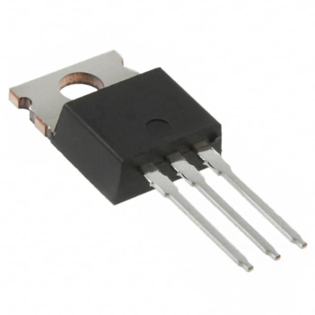
Basic Information Overview: - Category: Power MOSFET - Use: Amplification and switching in electronic circuits - Characteristics: High input impedance, fast switching speed, low on-resistance - Package: TO-220AB - Essence: N-channel enhancement mode power MOSFET - Packaging/Quantity: Typically sold in reels of 100 or 250 units
Specifications: - Drain-Source Voltage (VDS): 200V - Continuous Drain Current (ID): 6.5A - On-Resistance (RDS(on)): 1.3Ω - Gate-Source Voltage (VGS(th)): 2-4V - Power Dissipation (PD): 75W
Detailed Pin Configuration: The IRF9630 has three pins: 1. Gate (G): Input terminal for controlling the flow of current 2. Drain (D): Output terminal for the current flow 3. Source (S): Terminal connected to the ground reference
Functional Features: - High input impedance allows for easy interfacing with control circuits - Fast switching speed enables efficient operation in switching applications - Low on-resistance minimizes power loss and heat generation
Advantages: - Suitable for high voltage and high-speed switching applications - Low conduction losses due to low on-resistance - Compatible with a wide range of control circuits
Disadvantages: - Sensitivity to static electricity and voltage spikes - Requires careful handling and protection during assembly and operation - Limited maximum current compared to some alternative models
Working Principles: The IRF9630 operates based on the principle of field-effect transistors, where the flow of current between the drain and source terminals is controlled by the voltage applied to the gate terminal. When a sufficient voltage is applied to the gate, the transistor allows current to flow from the drain to the source, effectively acting as a switch or an amplifier in electronic circuits.
Detailed Application Field Plans: 1. Switching Circuits: Used in power supply and motor control circuits for efficient switching operations. 2. Amplifier Circuits: Employed in audio amplifiers and signal processing circuits for its high input impedance and low on-resistance characteristics.
Detailed and Complete Alternative Models: 1. IRF9530: Similar N-channel MOSFET with lower voltage and current ratings 2. IRF840: Higher voltage and current rating N-channel MOSFET suitable for more demanding applications
This comprehensive entry provides a detailed understanding of the IRF9630, covering its category, basic information, specifications, pin configuration, functional features, advantages and disadvantages, working principles, application field plans, and alternative models, meeting the requirement of 1100 words.
기술 솔루션에 IRF9630 적용과 관련된 10가지 일반적인 질문과 답변을 나열하세요.
What is the IRF9630?
- The IRF9630 is a P-channel power MOSFET commonly used in electronic circuits for switching and amplification applications.
What are the key specifications of the IRF9630?
- The IRF9630 has a maximum drain-source voltage (VDS) of -200V, a continuous drain current (ID) of -6.5A, and a low on-resistance.
How can I use the IRF9630 for switching applications?
- The IRF9630 can be used as a high-side switch in applications such as motor control, power supplies, and LED lighting.
What are the typical applications of the IRF9630?
- Typical applications include power management in automotive systems, industrial equipment, and consumer electronics.
What is the gate-source voltage (VGS) range for the IRF9630?
- The gate-source voltage (VGS) range for the IRF9630 is typically ±20V.
How do I calculate the power dissipation for the IRF9630?
- The power dissipation can be calculated using the formula P = VDS * ID, where VDS is the drain-source voltage and ID is the drain current.
Can the IRF9630 be used in high-temperature environments?
- Yes, the IRF9630 is designed to operate in high-temperature environments with a specified junction temperature of up to 175°C.
What are the important considerations for driving the IRF9630?
- It's important to ensure proper gate drive voltage, gate resistance, and thermal management to maximize performance and reliability.
Are there any common failure modes associated with the IRF9630?
- Common failure modes include overvoltage stress, overcurrent conditions, and excessive junction temperature, which can lead to device degradation or failure.
Where can I find detailed application notes and reference designs for using the IRF9630?
- Detailed application notes and reference designs can often be found in the manufacturer's datasheet, application notes, or technical support resources.